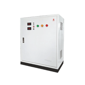
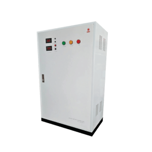
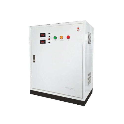
Central Battery Control Unit
CCU 24-500 To CCU 24-2200 (Figure C)
Central Battery Control Unit by CCU Series or the central control unit is used to detect any abnormalities of the main power distribution system. In case of error or emergency, the unit is designed to allow the emergency lighting system to bear large loads or larger loads than that the automatic emergency light (complete unit) can. The 24 VDC unit is compatible with halogen lamp or MR16 LED lamp. The unit installation and usage are centrally controlled so that it supplies power to the lamp installed
Technical Specifications
Mode of Operation | Non-Maintained |
Input Voltage | 220 VAC / 50Hz ± 10% |
Output Voltage | 24VDC |
Maximum Power Load | 500W, 600W, 700W, 950W, 1100W, 1200W, 1440W, 1700W, 1900W, 2200W |
Battery Type / Size | Sealed Lead-Acid Maintained Free 12V 55Ah x 2,12V 65Ah x 2,12V 40Ah x 4,12V 100Ah x 2, 12V 130Ah x 2,12V 65Ah x 4,12V 150Ah x 4, 12V 200Ah x 2,12V 130Ah x 4 |
Protections | • AC. Fuse. • AC,DC. Circuit Breaker. • Output Circuit Breaker. • AC. Input Over & Under VoltageProtection. • Battery Low Voltage Cut-Off. |
Testing Systems | Manual Testing |
Charging Mode | Constant Voltage & Limit Current |
Charging Time | 10-15 Hrs. |
Backup Time | 2.0 Hrs. |
Housing | Electro-galvanized steel sheet 1mm. thick with epoxy powder coating. |
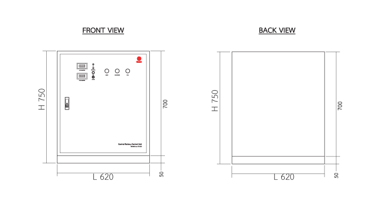
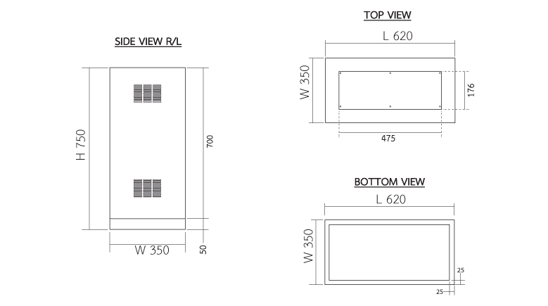
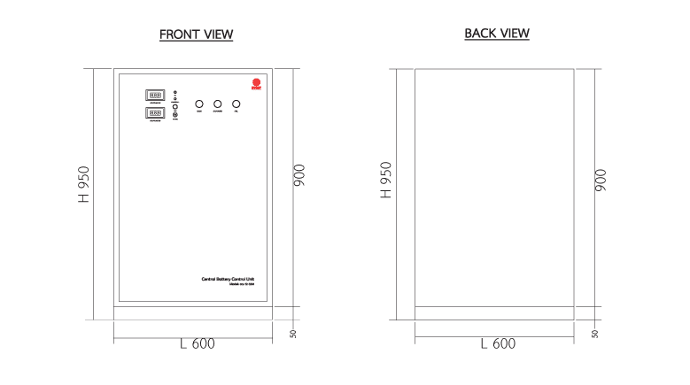
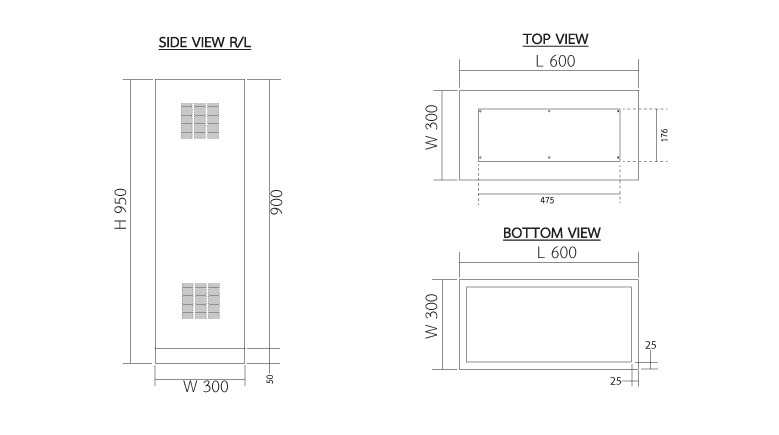
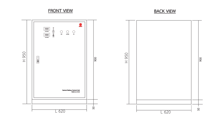
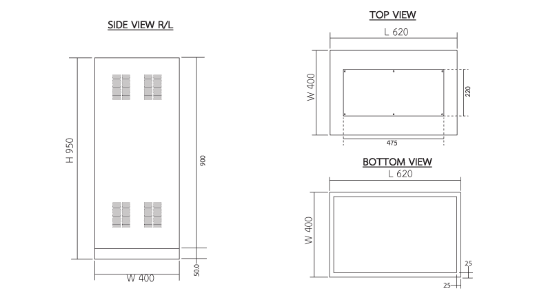
Dimensions (LxWxH) | 620 x 350 x 750 mm. 600 x 300 x 950 mm. 620 x 400 x 950 mm. |
Weight | 63.10-228.00 Kg. |
IP Rating | 20 |
Features
- Allowing testing with a switch on the front panel.
- Automatically recharged with constant voltage and limited current.
- Battery overcharge protection circuit prevents overcharge which is the cause of battery swelling.
- Battery discharge protection circuit prolongs the battery life.
- Under voltage protection circuit allows the unit to automatically activate the emergency light in case any fault occurs in the the main power distribution system or in case of power failure (140-160 VAC).
- Over voltage protection circuit allows the unit to automatically activate the emergency light in case any fault occurs in the the main power distribution system or in case of power failure (260-270 VAC
Indicators
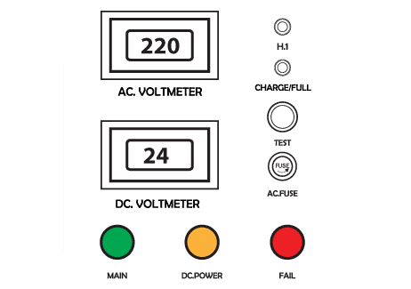
AC. VOLTMETER | Indicating the input voltage. |
DC. VOLTMETER | Indicating the battery voltage. |
LED H1 | Indicating the status of the input under voltage or over voltage. |
LED Charge/Full | Indicating charging status. |
SWITCH TEST | For testing the device’s availability (during normal circumstance) |
AC. FUSE | Short-circuit protection of AC input. |
LED MAIN | Indicating the status of the input voltage of 220VAC. |
LED DC.POWER | Indicating the status of the output voltage. |
LED FAIL | Indicating the failure status of the control unit. |
CCU 24V Series (Figure C) | Spec Sheets
Model | Power (Wattage) | Battery Capacity | Back up (hr.) | Length (mm) | Width (mm) | Height (mm) | Weight (kgs.) |
|---|---|---|---|---|---|---|---|
CCU 24-500 | 500 | 12V 55Ah x 2 | 2.0 | 600 | 350 | 750 | 63.10 |
CCU 24-600 | 600 | 12V 65Ah x 2 | 2.0 | 600 | 300 | 950 | 74.70 |
CCU 24-700 | 700 | 12V 40Ah x 4 | 2.0 | 600 | 300 | 950 | 100.00 |
CCU 24-950 | 950 | 12V 100Ah x 2 | 2.0 | 600 | 300 | 950 | 104.00 |
CCU 24-1100 | 1100 | 12V 130Ah x 2 | 2.0 | 600 | 300 | 950 | 130.00 |
CCU 24-1200 | 1200 | 12V 65Ah x 4 | 2.0 | 620 | 400 | 950 | 135.00 |
CCU 24-1440 | 1440 | 12V 150Ah x 4 | 2.0 | 620 | 400 | 950 | 136.00 |
CCU 24-1700 | 1700 | 12V 200Ah x 2 | 2.0 | 620 | 400 | 950 | 181.00 |
CCU 24-1900 | 1900 | 12V 200Ah x 2 | 2.0 | 620 | 400 | 950 | 181.00 |
CCU 24-2200 | 2200 | 12V 130Ah x 4 | 2.0 | 620 | 400 | 950 | 228.00 |

